Tests were done with a Futaba 8UHFS. We have not yet verified that the menus are identical in the original 8U - if you have one and can test this for us we'll be happy to hear from you.
You'll notice that some of the screens in Menu Mode 2 are repeats of those in Menu Mode 1. For completeness and clarity, images and descriptions are given in both sections.
When accessing menus in the 8U, remember the following:
- You can scroll between screens using the MODE buttons
- In Menu Modes 1 & 2 you can't scroll past the first screen until both up and down MODE buttons have been pressed
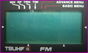
8U Service Menu Mode 1
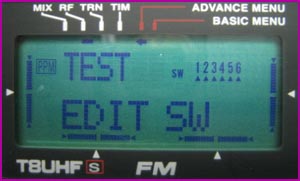
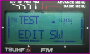
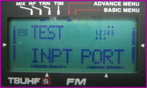
This first screen lets you test for correct operation of the 6 input buttons. As you press each button its corresponding arrow will dissapear.
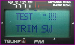
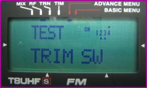
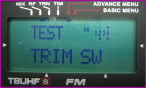
Same as the button test, but tests the 4 trim buttons. Move each trim in both directions and watch the arrows disappear.
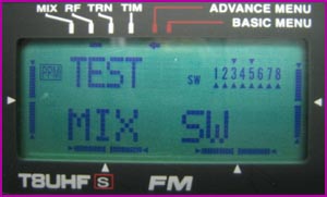
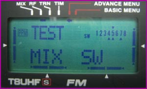
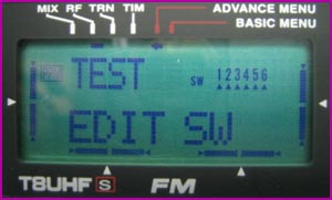
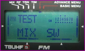
Tests the toggle switches on the radio. Before this test will work, all toggle switches must be in their home position - this means all 2-position switches are up, and all 3-position switches are centered. Only when all switches are at their home positions will the test start. Now you can toggle each switch back and forth and arrows will appear for each switch. During the test each switch must always be returned to its home position - a switch cannot be tested until all other switches are at their home position. If a switch is not returned to its home position the switch number will blink.

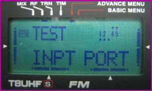
This screen appears to show the status of the CAMPac port, and possibly the buddy box jack on the back of the radio. If you remove the 256K module, for example, number 1 will stop blinking.
This is simply a display test that blinks the entire display on and off so you can check for dead pixels.
8U Service Menu Mode 2
This first screen lets you test for correct operation of the 6 input buttons. As you press each button its corresponding arrow will disappear.
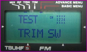
Same as the button test, but tests the 4 trim buttons. Move each trim in both directions and watch the arrows disappear.
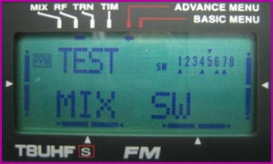
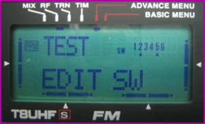
Tests the toggle switches on the radio. Before this test will work, all toggle switches must be in their home position - this means all 2-position switches are up, and all 3-position switches are centered. Only when all switches are at their home positions will the test start. Now you can toggle each switch back and forth and arrows will appear for each switch. During the test each switch must always be returned to its home position - a switch cannot be tested until all other switches are at their home position. If a switch is not returned to its home position the switch number will blink.
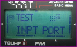
This screen appears to show the status of the CAMPac port, and possibly the buddy box jack on the back of the radio. If you remove the 256K module, for example, number 1 will stop blinking.
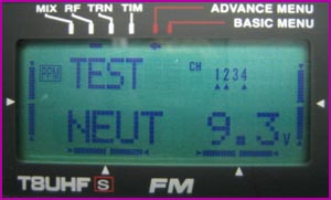
This seems to be some sort of voltage calibration. We're not sure how it works yet.
On this screen and the next you can set the endpoints of your radio sticks and knobs. You can calibrate the sticks and knobs all at once, or you can calibrate one thing at a time. Just move the TX sticks down and to the right, and turn the knobs all the way clockwise and press the "+" button to set the endpoint. For each stick/knob that you calibrated its arrow will disappear. You do not have to calibrate everything.
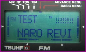
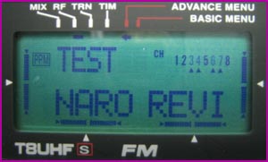
Now set the other end of the range by moving the sticks up and to the left, and turning the knobs all the way counter-clockwise. Press the "+" button and watch the arrows disappear.
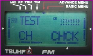
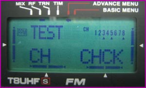
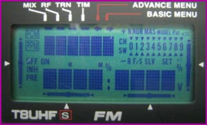
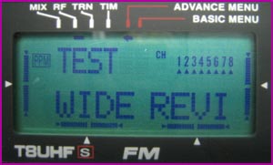
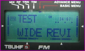
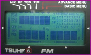
Channel check. Not sure exactly what this is checking for, but here's how it works: Start with the sticks and knobs centered, and all toggle switches to home positions. The test also works with everything starting at the NARO position. Everything has to be moved separately to its WIDE position; slowly move each stick down and back to/past center, then right and back to/past center; toggle switch G to check channel 5; turn each knob fully clockwise and back to/past center for channels 6-8. As you do this the arrows will disappear. If at any time more than one channel is moved toward WIDE you'll get blinking numbers indicating which ones.
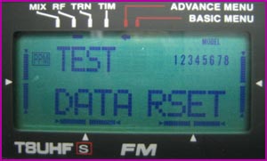
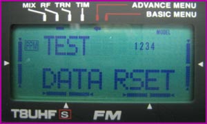
WARNING!!! This screen lets you erase all model data stored on your radio. You can skip the screen by pressing "MODE^". If you want to erase your models press "+". Each model will be erased and you'll see the numbers disappear as it goes.
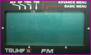
This is simply a display test that blinks the entire display on and off so you can check for dead pixels.
8U Service Menu Mode 3
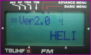
Radio firmware version and transmitter mode.
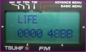
Press the right cursor from the previous screen to view this screen. Total on-time for the radio, probably in hours. We're not sure what the "C" means.

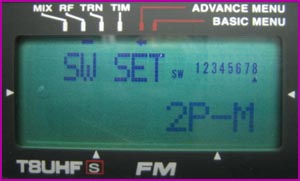
Lets you specify 2POS, 3POS, 2P-M, or VR for each toggle switch. 2P-M means momentary and refers to a 2-position switch that normally stays at its home position like the trainer switch (switch H). VR probably refers to the side adjustments like on the 9C. Use the cursor keys to scroll among switches, and using the "+/_" keys to select the switch type. Making these changes work probably requires doing a little rewiring in your radio.
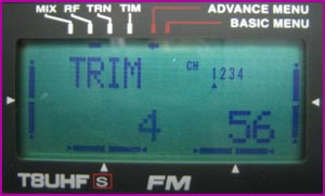
Not certain exactly what this does. It lets you change both numbers for each stick.